
Inverter is also called power regulator. The process of converting DC power into AC power is called inversion. The circuit that completes the inverting function is called inverting circuit. The device that realizes the inverting process is called inverting equipment or inverter. In solar power generation system, the efficiency of inverters is an important factor to determine the capacity of solar cells and storage batteries. The failure of photovoltaic inverters will lead to the shutdown of photovoltaic system, which will directly cause the loss of power generation. Therefore, high reliability is an important technical index of photovoltaic inverters.
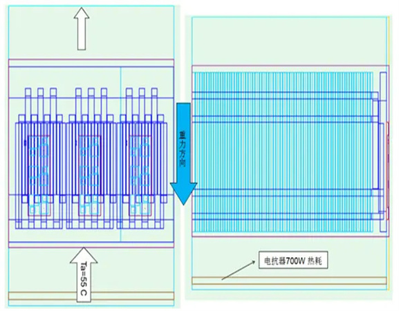
Ambient temperature:55⁰C
Reactor Heat Consumption:700W
Diode:59W; IGBT:124.5W; Total:1100WW;
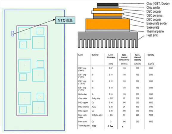
Assuming that the heat conducting medium is:0.15mm Thick,K=3W/m*K.
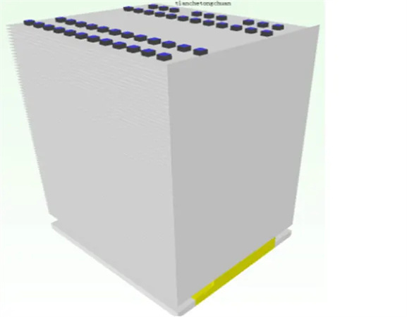
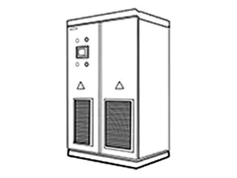
Size:W236*L200*H304mm
Thick:0.6mm
Pitch between teeth:3.0mm
Number of teeth:77fins
Heat pipe parameters:
D8 Sintered tube or fibre tube;
Use 24pcs U heat pipe (one layer layout) and type 48 PCs L heat pipe (two layers layout);
Welding with 4258 low temperature solder paste;
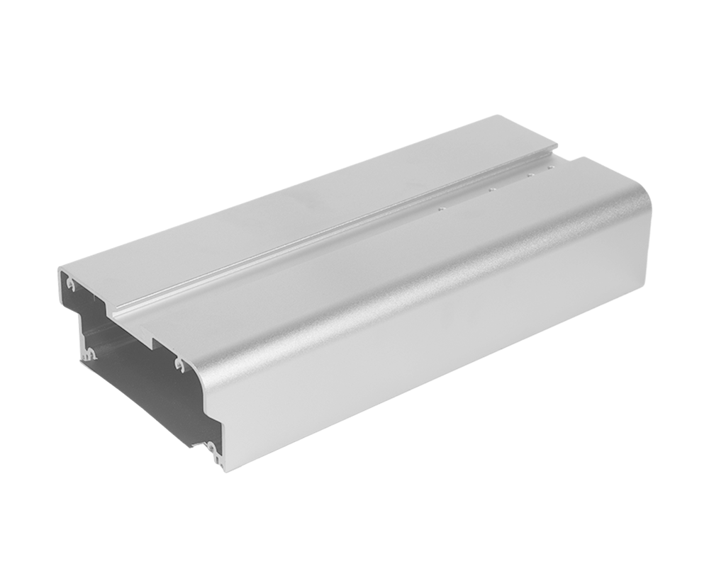
Substrate: AL Plate + Copper Plate (IGBT Heat Source Area)
Compared with two-layer heat pipe, one-layer heat pipe has lower cost and higher heat dissipation efficiency.
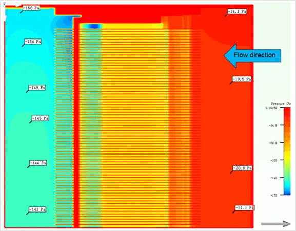
Simulation sketch of pressure diffusion degree of section in module
Simulation sketch of pressure diffusion degree of section in module
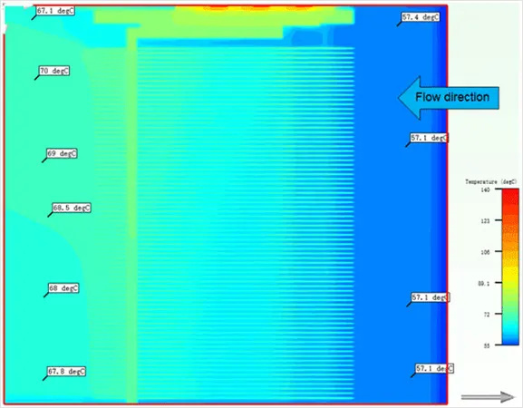
Temperature Diffusion Simulation Diagram of Section in Module
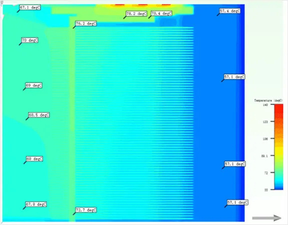
The temperature difference between the two ends of the heat pipe is 5.7 degrees, which meets the actual heat pipe standard.
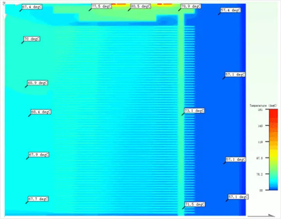
Temperature diffusion simulation sketch of bottom heat pipe
Temperature Diffusion of Heat Pipe at the Bottom of Radiator
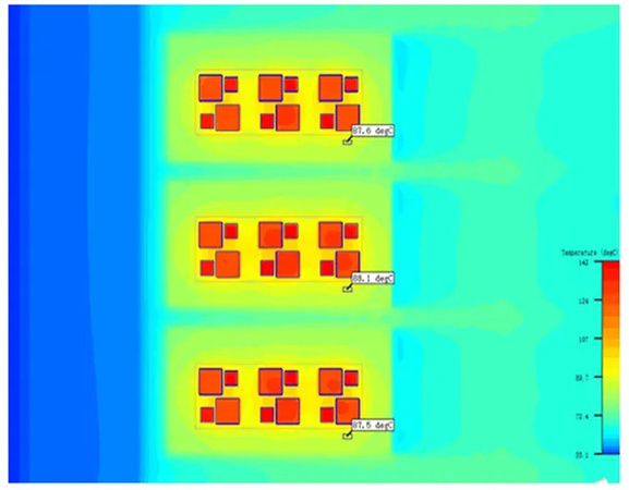
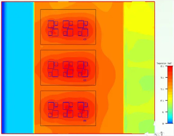
NTC Temperature Diffusion Simulation Diagram of Module
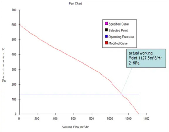
Diagram of Fan Action Point
 +86 18879690228
Email: Harvey@greenwayalu.com
Headquarters: Floor 5, Building B,GS Industry Park, Longhua District, Shenzhen518109,China.
Dongguan factory: Shishuikou Industrial Park, Qiaotou Town, Dongguan City, Guangdong Province,China.
©2013 GREENWAY All rights reserved


 CN
CN Home >