
According to the provisions of the State Grid, the proportion of distributed generation such as photovoltaic and wind power should not exceed 10% of the power grid, and more than 10% of the grid will be added to the energy storage system. Because photovoltaic system and wind power system do not use energy storage system in grid-connected power generation, there will be some adverse effects on the grid. If the scale of wind energy and photovoltaic power system continues to expand and the proportion of photovoltaic power in the system continues to increase, these effects can not be ignored. Through the analysis of the characteristics of photovoltaic power generation, it can be seen that the impact of photovoltaic power generation system on the grid is mainly caused by the instability of photovoltaic power supply. In order to make the grid safer, stable and economic operation, it is generally required to install energy storage system. Therefore, the demand for energy storage system has increased in recent years.
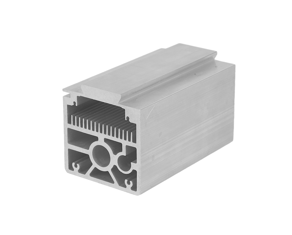
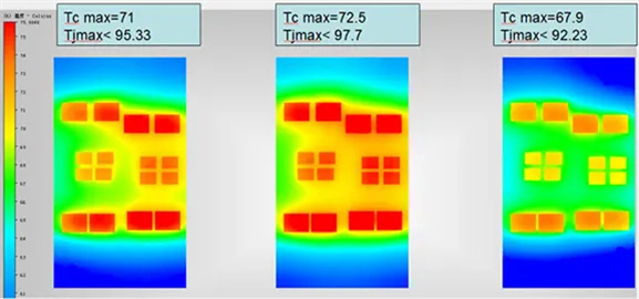
IGBT:317.2W,No additional heat consumption;
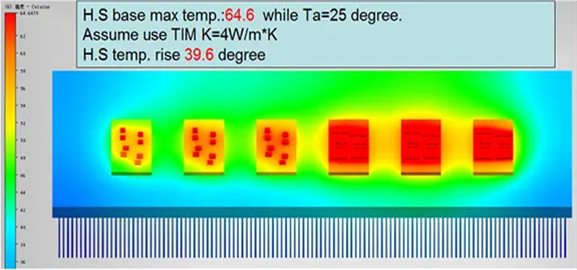
Thermal conductive medium:0.1MM,K=4W/m*K;
IGBT Rjc=0.74K/W,diode Rjc=0.84 K/W
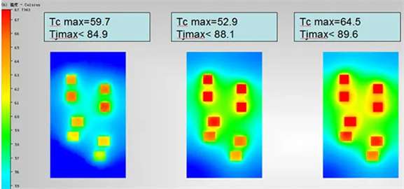
IGBT:223.8W,No additional heat consumption;
Thermal conductive medium:0.1MM,K=4W/m*K;
IGBT Rjc=0.65K/W diode Rjc=0.86
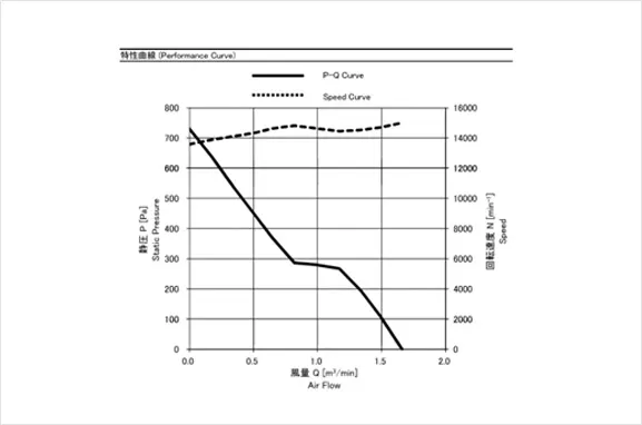
Use Minebea06038DA-12R-EUD-1 15000RPM Fan
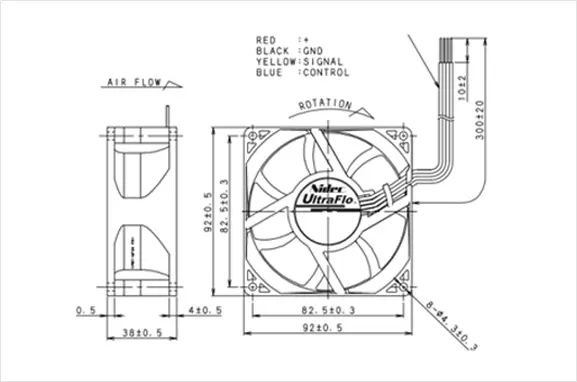
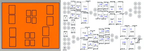
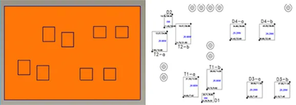
Simulated sketch of fan usage
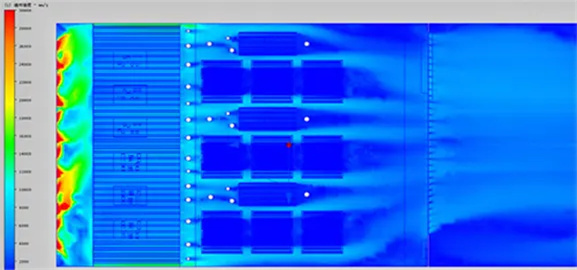
Simulation sketch of cross-section dissipation velocity in inverter radiator of energy storage system
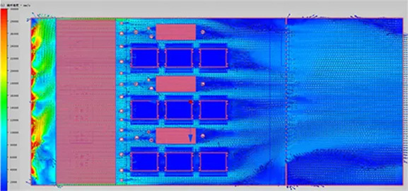
Simulation sketch of cross-section vector dissipation in inverter radiator of energy storage system
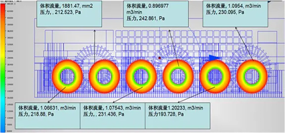
The simulation result and schematic diagram of airflow vector dissipation
INV Temperature Dissipation Simulation and Schematic Diagram of Modular Radiator
Temperature Dissipation Simulation and Schematic Diagram of Inverter Radiator
RFC Temperature Dissipation Simulation and Schematic Diagram of Modular Radiator
 +86 18879690228
Email: Harvey@greenwayalu.com
Headquarters: Floor 5, Building B,GS Industry Park, Longhua District, Shenzhen518109,China.
Dongguan factory: Shishuikou Industrial Park, Qiaotou Town, Dongguan City, Guangdong Province,China.
©2013 GREENWAY All rights reserved


 CN
CN Home >